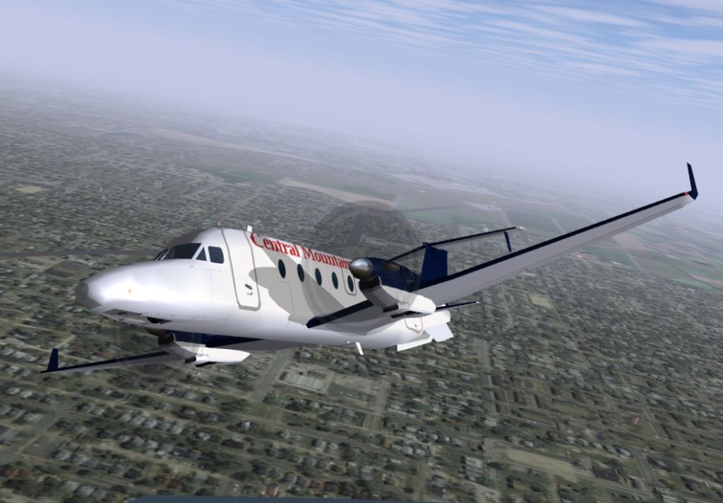
Flightgear Planes

Apr 12, 2020 So, Since the new flightgear update, 2019.1.1, the Boeing 737YV has been messed up. The flightdeck screens are off, even when I auto start the aircraft. I can click on them and they show up in the window, but they don't do anything. The autopilot is also off in the flightdeck so I cant use it there.
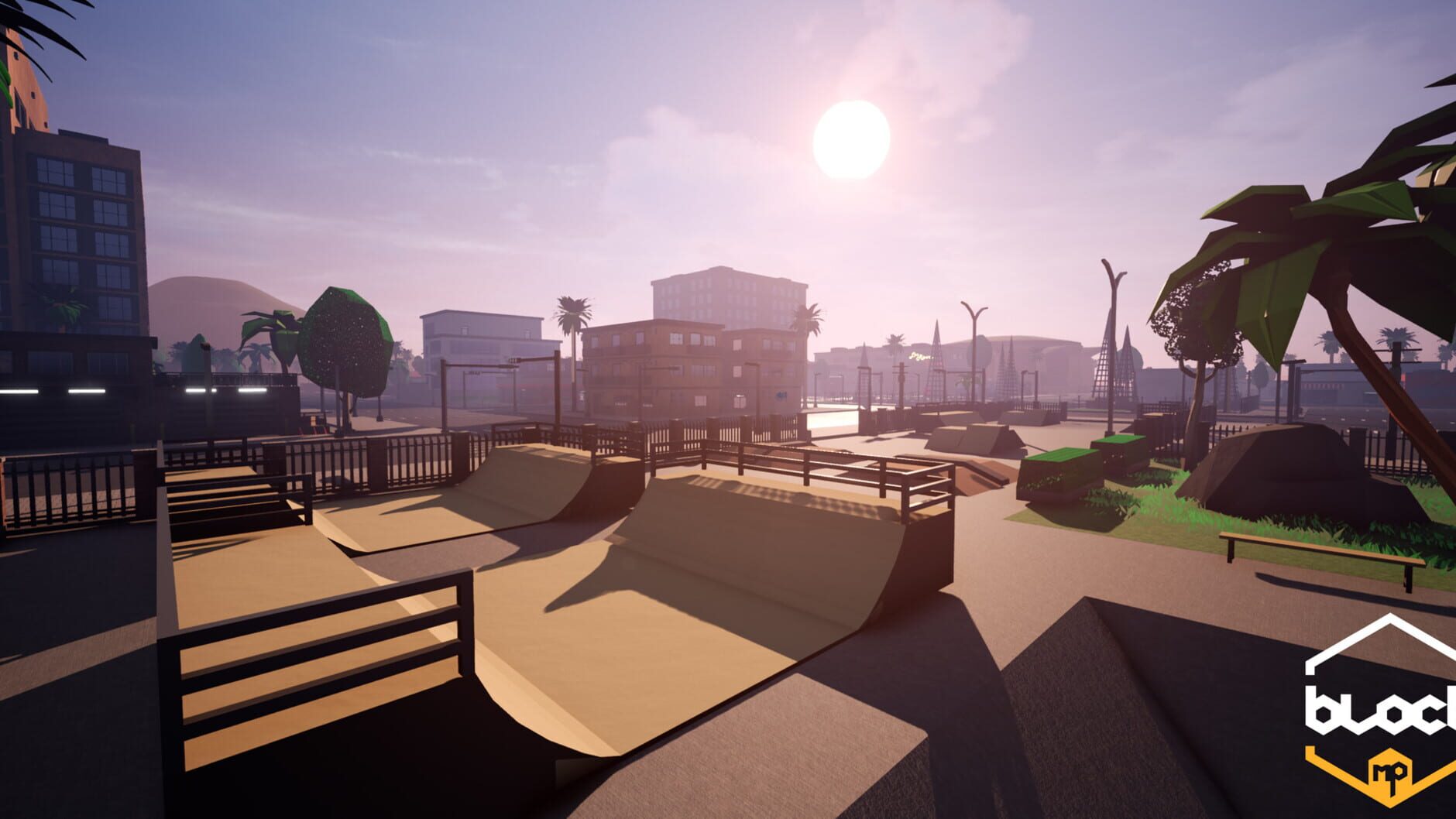
Cybermotion is 2D platformer based on physics. Players are able to make own unique animations that define how the robot moves through the environment. Thre are no NPC enemies. The goal is to finishing levels in time and win bronze, silver or gold medal. Cybermotion is 2D parkour platformer based on physics. Players are able to make own unique animations that define how the robot moves through the environment. The goal is to finishing levels in time and win bronze, silver or gold medal. Cybermotion is physics based platformer. You play as a student project robot that's constantly beeing tested by its creators. Combine physics animations and poses to move through the levels full of obstacles.  CyberMotion Games presents you the online role-playing game Block Multiplayer RPG, which will certainly fascinate all the players! The new project will combine a favorite and familiar RPG gameplay with notes of unique innovations.
About Aircraft Geometry ModelsBefore you can visualize your aircraft dynamics, you need to create or obtain an aircraftmodel file compatible with FlightGear. This section explains how to do this. Aircraft Geometry Editors and FormatsYou have a competitive choice of over twelve 3-D geometry fileformats supported by FlightGear.Currently, the most popular 3-D geometry file format is the AC3D format, which has the suffix.ac. AC3D is a low-cost geometry editor available from. Aircraft Model Structure and RequirementsAircraft models are contained in the FlightGearRoot /data/Aircraft/ folderand subfolders. A complete aircraft model must contain a folder linkedthrough the required aircraft master file named model -set.xml.All other model elements are optional.
This is a partial listof the optional elements you can put in an aircraft data folder. Network Obtain and Modify Existing Aircraft ModelsYou can quickly build models from scratch by referencing instruments,sounds, and other optional elements from existing FlightGear models.Such models provide examples of geometry, dynamics, instruments, views,and sounds. It is simple to copy an aircraft folder to a new name,rename the model -set.xml file,modify it for network flight dynamics, and then run FlightGear withthe –aircraft flag set to the name in model -set.xml.Many existing 3-D aircraft geometry models are available for use with FlightGear. Visit thedownload area of to see some ofthe aircraft models available. Additional models can be obtained via Web search.Search key words such as “flight gear aircraft model” are a goodstarting point. Be sure to comply with copyrights when distributing thesefiles.
Hardware Requirements for Aircraft Geometry RenderingWhen creating your own geometry files, keep in mind that yourgraphics card can efficiently render a limited number of surfaces.Some cards can efficiently render fewer than 1000 surfaces with bitmapsand specular reflections at the nominal rate of 30 frames per second.Other cards can easily render on the order of 10,000 surfaces.If your performance slows while using a particular geometry,gauge the effect of geometric complexity on graphics performance byvarying the number of aircraft model surfaces. An easy way to checkthis is to replace the full aircraft geometry file with a simple shape,such as a single triangle, then test FlightGear with this simplergeometry. If a geometry file is too complex for smooth display, usea 3-D geometry editor to simplify your model by reducing the numberof surfaces in the geometry. Work with Aircraft Geometry ModelsOnce you have obtained, modified, or created an aircraft datafile, you need to put it in the correct folder for FlightGear to accessit. Import Aircraft Models into FlightGearTo install a compatible model into FlightGear, use one of thefollowing procedures.
Choose the one appropriate for your platform.This section assumes that you have read.If your platform is Windows. $FlightGearBaseDirectory/FlightGear.app/Contents/Resources/data/Aircraft/.Make a subfolder model/here for your aircraft data.Put model -set.xml inthat subfolder, plus any other files needed.It is common practice to make subdirectories for the vehiclegeometry files ( /model/), instruments ( /instruments/),and sounds ( /sounds/).Example: Animate Vehicle GeometriesThis example illustrates how to prepare hinge line definitionsfor animated elements such as vehicle control surfaces and landinggear. To enable animation, each element must be a named entity ina geometry file. The resulting code forms part of the HL20 liftingbody model presented in. RotateRightAileron/surface-positions/right-aileron-pos-norm3003.262.321.000.560.860.93Run FlightGear with Simulink ModelsTo run a Simulink model of your aircraft and simultaneouslyanimate it in FlightGear with an aircraft data file model -set.xml,you need to configure the aircraft data file and modify your Simulink modelwith some new blocks.These are the main steps to connecting and using FlightGearwith the Simulink software. Ipconfig /allExamine the IP address entry in the resulting output. There is oneentry per Ethernet device.Create a FlightGear Run ScriptTo start FlightGear with the desired initial conditions (location,date, time, weather, operating modes), it is best to create a runscript by or.If you make separate run scripts for each model you intend tolink to FlightGear and place them in separate directories, run theappropriate script from the MATLAB interface just before startingyour Simulink model.Use the Generate Run Script Block.
The easiest way to create a run script is by using the block. Use the followingprocedure.To direct FlightGear to automatically install requiredscenery while the simulator is running — SelectInstall FlightGear scenery during simulation(requires Internet connection). ForWindows systems, you may encounter an error messagewhile launching FlightGear with this option enabled. Formore information, see.To disable FlightGear shader options — SelectDisable FlightGear shaderoptions.Repeat steps 5 through 10 to generate other runscripts, if needed.Click OK toclose the dialog box. You do not need to save the Generate Run Scriptblock with the Simulink model.The Generate Run Script block saves the run script as a textfile in your working folder.
This is an example of the contents ofa run script file. cd C:ApplicationsFlightGear-2019.1 SET FGROOT=C:ApplicationsFlightGear-2019.1data cd bin fgfs -aircraft=HL20 -fdm=network,localhost,5501,5502,5503-fog-fastest -disable-clouds -start-date-lat=2004:06:01:09:00:00-disable-sound -in-air -enable-freeze -airport=KSFO -runway=10L-altitude=7224 -heading=113 -offset-distance=4.72 -offset-azimuth=0Use the Interface Provided with FlightGear. The FlightGear launcher GUI (part of FlightGear, not the AerospaceBlockset product)lets you build simple and advanced options into a visible FlightGearrun command. Start FlightGearIf your computer has enough computational power to run boththe Simulink software and FlightGear at the same time, a simpleway to start FlightGear on a Windows system is to create a MATLAB desktopbutton containing the following command to execute a run script likethe one created above.Make sure your model is in a writablefolder. Open the model, and update the diagram. This step ensuresthat any referenced block code is compiled and that the block diagramis compiled before running.